Linear motors are gaining increasing market share and usage, partly because end-users demand higher throughput and greater precision. The common perception of these systems is that they can operate at high speeds, offer long travel distances, and deliver high positioning accuracy—capabilities that other drive mechanisms cannot match. However, their advantages extend beyond these; they can also perform extremely slow, smooth, and precise movements. Specifically, this technology provides a broad and powerful set of capabilities: thrust, speed, acceleration, positioning accuracy, and repeatability, so there are few solutions or applications that cannot be enhanced with such equipment.
When such motors are the best choice for your application, there are three key things to consider during the initial selection process.
1. Core vs. Coreless linear motors: The Primary Consideration
1.1 Iron-Core Units
A drawback of the iron-core design is cogging, which reduces motion smoothness. Cogging occurs because the slotted design of the primary component gives it “preferred” positions as it moves along the row of magnets in the secondary component. To overcome the tendency of the primary to align with the secondary magnets, the unit must generate additional force to counteract this trend, leading to speed fluctuations known as cogging. These variations in force and speed can reduce motion smoothness, which can be a significant issue in applications where the quality of motion throughout the travel (not just final positioning accuracy) is critical.
Manufacturers use several methods to reduce cogging in these systems. One common approach is to skew the position of the magnets (or teeth), which results in smoother motion as the primary moves past the secondary magnets. A similar effect can be achieved by changing the magnet shape to an elongated octagon. Another method is segmented winding: in this design, the laminated teeth of the primary coil are more numerous than the magnets in the secondary, and the laminated stack has a special shape—these elements work together to counteract cogging forces. Additionally, software algorithms can adjust the current supplied to the primary coil, minimizing force and speed variations.
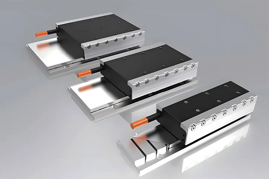
1.2 Ironless Units
These ironless units do not experience cogging because their primary coils are encapsulated in epoxy rather than wound around an iron core. They have a lower mass (epoxy is lighter than iron, though less rigid), enabling the highest acceleration, deceleration, and operating speeds in electromechanical systems. Their settling time is typically better (lower) than that of iron-core units, and the absence of cogging or speed ripples means they can provide very low-speed, stable motion—usually with speed fluctuations of less than 0.01% during low-speed operation.
2. How Integrated Should Your System Be?
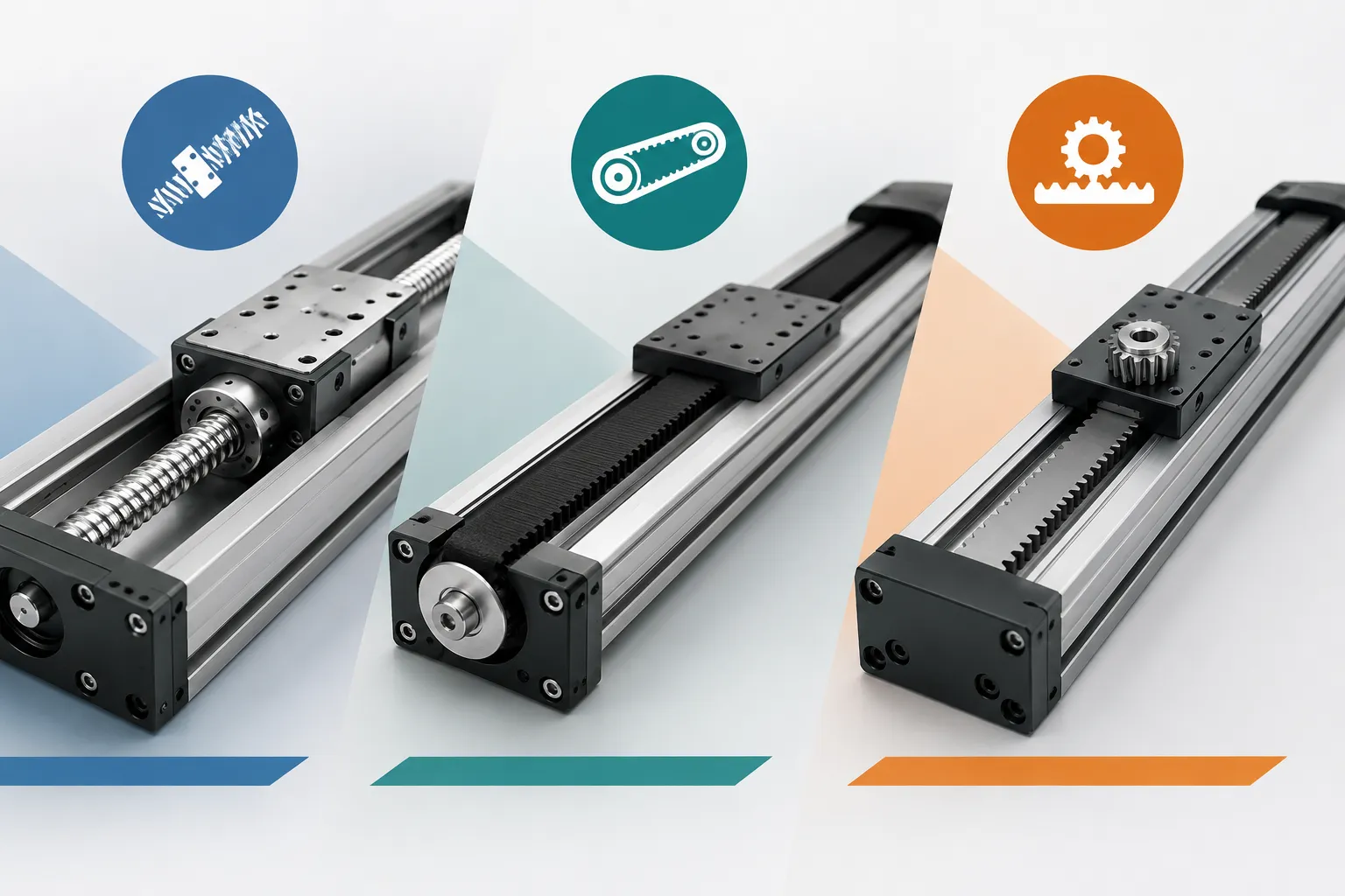
Like rotary motors, linear motors are just one component in a motion system. A complete setup also requires bearings (guides) to support and guide the load, cable management, feedback (usually a linear encoder), servo drives, and controllers. Experienced equipment manufacturers or those with unique requirements can build custom systems using in-house capabilities and off-the-shelf components from various suppliers.
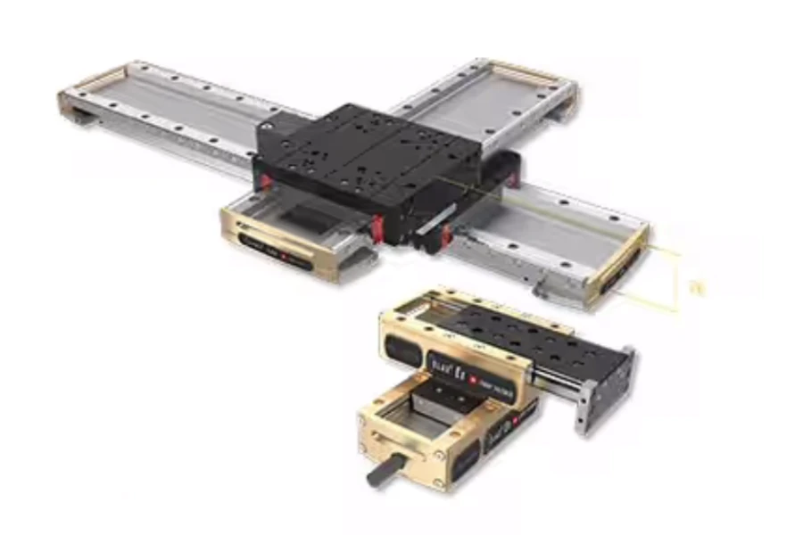
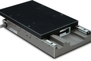
Designing such a system can be simpler than setups based on belts, rack-and-pinion, or lead screws: it has fewer components and less labor-intensive assembly steps (no need to align ball screw supports or tension belts). These units are non-contact, so designers don’t have to plan for drive unit lubrication, adjustment, or maintenance. For OEMs and machine builders seeking turnkey solutions, there are countless options for complete driven actuators, high-precision stages, and even Cartesian and gantry systems.
For DIY enthusiasts selecting guides for iron-core units, note that the attractive force between primary and secondary components can increase the load on linear guides. Ironless systems avoid this issue, as their primary section has no iron core (and thus no attractive force between components).
3. Is the Working Environment Compatible?
Linear motors are often the preferred solution in specialized environments like cleanrooms and vacuum settings. They have fewer moving parts and can pair with almost any linear guide or cable management to meet requirements for particle generation, outgassing, and temperature. In extreme cases, the secondary (magnetic track) can act as the moving part, while the primary (windings, cables, and cable management) stays stationary.
However, these units may not be ideal if the environment contains metal shavings, dust, or particles—especially iron-core designs, whose open structure exposes the magnetic track to contamination. Ironless units’ semi-enclosed design offers better protection, but care should be taken to keep secondary component slots away from contamination sources. Enclosed versions for both types solve contamination issues but reduce heat dissipation, potentially trading one problem for another.
In conclusion, selecting the right linear motors requires aligning your application’s needs with core factors: choosing between iron-core (high thrust) and ironless (smooth, high-speed) designs, defining the required system integration level (custom builds vs. turnkey solutions), and verifying environmental fit. By addressing these points, you can leverage the versatility of these systems—from high-speed precision to low-speed stability—to optimize your motion setup’s performance. As these solutions continue to advance, they remain an increasingly valuable choice for diverse industrial and technical applications.